Questions ? Call us at 905-624-5536. |
|||||
|
|||||
|
||||||||||
Annn Yang 2000 x 15M lathe, This is a light version customized for deep hole drilling |
  Headstock and carriage of a machine raised to give 2000 mm swing. The center distance is 50 feet. This series of pictures are of a high capacity, light duty machine built up on a bed 692 mm wide. For heavier work machines can be built on beds 888, 1150 oand 1400mm wide and carry loads to 20 tons. The carriage has a steady on it which is part of a deep hole drilling system. |
 2000 x 15M lathe with 2 carriages. The second carriage near the tailstock provides the feed to the deep hole drilling system. Behind the machine is the huge cutting oilt tank with a chip conveyor on top to collect chips fromt the deep hole drilling system. |
 |
 |
 In the picture above you can see the steady mounted on the carriabe near the headstock and the feed carriage near the tailstock. This carriage has a self container variable speed drive for the feed, which is easier to see in the photo below. |
|
 |
 |
 |
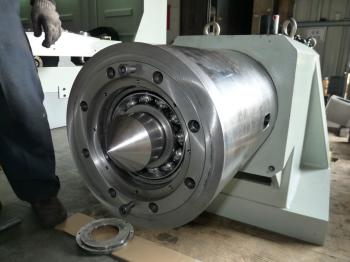 A super heavy duty tailstock with built in live center. The bearing cover is removed to show the bearings With one steady rest this can support 40 metric tons on the heavier Annn Yang lathe models. |
 This picture shows a short section of chip conveyor on top of a high capacity coolant tank. With huge flow rates for the deep hole drilling, a large tank is required. |
 The wide range 2 point steady rest. Intended for heavy parts that do not need the top roller. |
|
 A 2000G series lathe drilling a deep hole through the center of a long part in a shipyard. The part in the foreground has a 70mm hole through it. |
 A view of the carraiges supporting and pushing the drill bar. The coolant delivery pipe ( gray ) can be seen coming from the 5000 Gallon tank behind the machine. In this specialized system the coolant is pumped into the hole on the outside of the tool and the chips get flushed back through the center of the drill. |
 This picture shows the set up of the two carriages to support and push the drill. We beleive the coolant is injected just infront of the end of the part through a sealed coupling bolted to the end of the part and the yellow box on the bed collects the leaks. Note that there are no chips or coolant visible anywhere. The coolant delivery piping is hidden by the toolpost. On the picture below you can see this. |
Again note the neatness of the shop, no chips or coolant anywhere. The coolant delivery pipe going to the front carriage is visible. The end of the drill has a flange and recovery pipe that is just visible at the left edge of the picture. The recover pipe and travelling splash cart is visible in the picture below. |
 Here the chip and coolant recovery system is visible. The coolant / chip recovery tank behind the machine is approximately 1/2 the length of the lathe bed. The chip cart on top of the coolant tank travels as the drill bar feeds into the part. The primary purpose of the cart is to prevent splash and direct the coolant and chips onto the conveyor on top of the tank. |
 Here is the 15 Hp high pressure coolant pump. The delivery is 125 GPM at 290 PSI The tank holds over 5000 gallons of coolant. |
 The gate and check valves between the tank and pump |
 This is the rotary union for the cutting oil injection. The deep hole drill bit and a bit of the drill rod is projecting from the union. The end of the workpeice is faced smooth and the union is pushed by the steady carriage against the smooth face and sealed by the large O-ring that can be seen on the face of the union. |