| Questions ? Call us at 905-624-5536 |
|||||
|
|||||
|
||||||||||
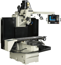
| HH Roberts / Topwell TW-32-Q Bed Style CNC Mill with tilting quill type head travels 32" x 20" x 20", 7 1/2 to 15 Hp 6,000 rpm manual hand wheels on X and Y quill lever on the head |
 Below our TW-32-Q at the Toronto Machine Tool Show October 2015 On the Heidenhain booth 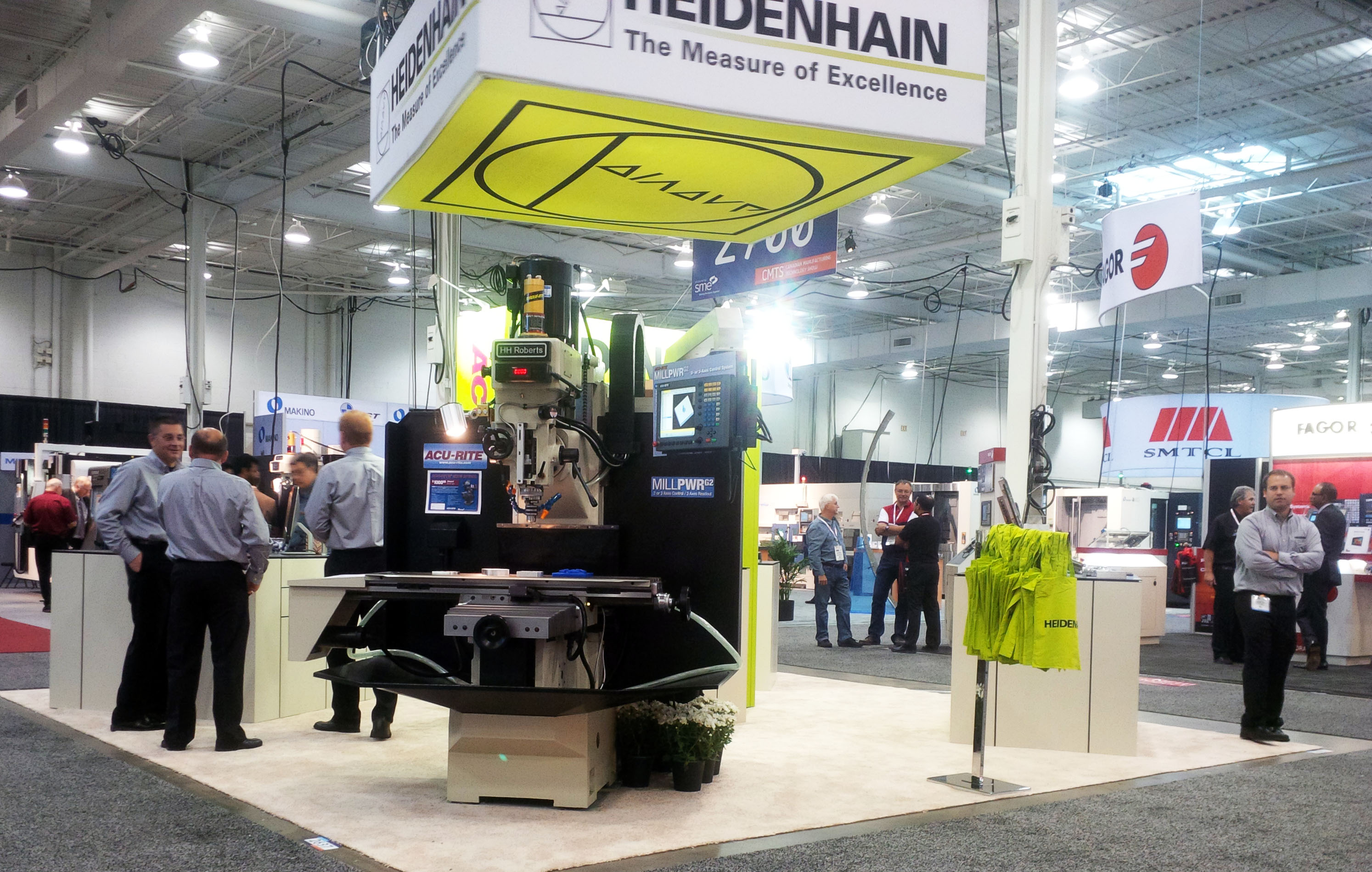 |
|
|
||||||||||||
|
|
| This machine can be offered with Anilam controls or Heidenhain. The chip pan, side splash guards, coolant pump, telescopic steel covers, power draw bar and work light are all standard. The spindle can accept either standard # 40 tools, CAT-V 40 or BT-40 tools. We also offer a manual machine with the same machine frame, ballscrews, and CNC servo axis feed system and and integral digital readout. Because the feed system uses the same series CNC motors and amplifiers, a future upgrade to a full CNC is easy and economical. We use CDS DC Servo drivers on these machines as standard equipment. Click here to see the manual model |
| TW-32-Q | |
| X axis travel | 32" opt 28" |
| Y axis travel | 20" |
| Z axis travel | 20" |
| Quill travel | 5" |
| Quill power feeds | 3 |
| Table size | 50" x 12" |
| Spindle C/L to column | 22" optionally 25" |
| Spindle nose to table | 23" |
| Saddle width | 22" |
| Tooling | Cat-V40, BT-40 or NMTBA-40 |
| Tool clamping standard | pneumatic power draw bar |
| Spindle bearing ID | 50 mm |
| Spindle power * | 7 1/2 Hp standard, optionally 12 or 15 Hp. |
| Spindle speeds standard | direct drive 100 to 6,000 or 75 4000 |
| Spindle speeds optional | Back geared, Low 15 to 750 --- High 100 6,000 rpm |
| Rapid traverse | 250 IPM |
| Axis motor torque - cont. | stardard DC 3.1 NM optional 4.5 or Yaskawa AC 5.3 |
| Main power supply | 230/3/60 optionally 220/1/60 or 460/3/60 |
| Aprroximate weight (lbs) | 4,450 |
| Floor space L-R x F-B | 97" x 102" opt 75" x 102" |
| Max. height in operation | 101" |
| With Handwheels or Without ??? Many customers originally want handwheels on a machine like this. Giving up the ability to grab the handwheel is sometimes a difficult mental thing to adjust to. Very few applications can be done as well with handwheels as under CNC control.
So, why not ? The electronic handwheels ( sometimes called MPG's ) give you better control than the mechanical handwheel. To fit handwheels economically the table saddle construction must be similar to the familiar Bridgeport arrangement. This means the saddle is narrower because the X axis handwheel will hit the side of the saddle. A narrow saddle is needed to give as much X axis travel as possible. The saddle support for the table suffers, especially near either end of the stroke where the table extends a long way. Another is that is not so obvious is that the economical way to construct the casting holding the X and Y axis ballscrew nuts, is on a common yoke, again like a Bridgeport. This give pretty good support the the X axis nut but the Y axis nut is suspended several inches lower, down between the Y axis slideways. As movements or cutting loads are applied, this extension permits a significant and measureable flex. In heavy cutting it results in chatter between the saddle and knee.You can check this yourself on any Bridgeport type mill. Set up a heavy cut and place your finger just where the saddle meets the cross slide. It will surprise you how much movement there is. Furthermore, the handwheels are never balanced well and at high rpm during rapid traverse, cause vibration, which means we must restrict the rapid traverse rate to about 300 rpm to avoid the vibration. The solution for both the support issue and the ballscrew nut issue is to built the machine with the same table / saddle design as modern machining centers. The saddle is very wide and gives excellent support to the table. The X and Y ballscrew nuts are mounted independently with minimal extension. The negative side, you can't put a handwheel on the end of the X axis screw, like a Bridgeport. Another solution is to build the machine like a machining center and drive the X axis screw through a 90 degree bevel gear arrangement. We recommend that you seriously consider our TW-31, with virtually the same capacity as the above TW-32, or our larger TW-40 which uses the 90 degree drive for the versions with handwheels. |